Dc motor speed control circuit diagram using 555 timer Based pwm timer 555 motor timer speed control circuit dc clock questions lab experiment cycle duty
Pin on Arduino
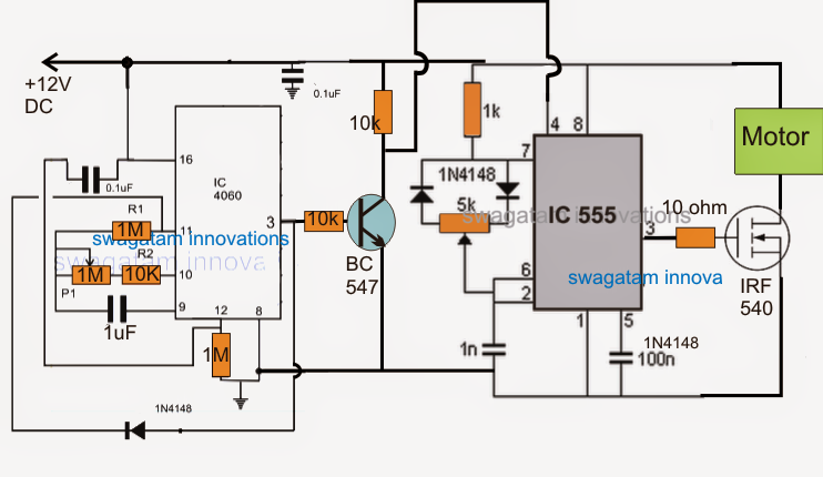
Motor irf540 control dc mosfet speed ne555 using pwm arduino Ic timer circuits pwm Motor timer dc control speed using ic electrosal
An electronic circuit diagram showing the current voltages and power
555 based dc motor speed controllerPwm motor speed controller with adjustable delay timer Simple dc motor controller using 555 timer icSimple dc motor speed control circuit diagram using ic 555 timer.
Dc motor speed control using ne555 and irf540 mosfetDc motor circuit diagram 555 dc motor controllerController speed timer.

Ic timer
555 dc motor speed control : 6 stepsSimple dc motor controller using 555 timer ic Motor circuit speed controller pwm timer delay circuits adjustable dc off homemade time based controlledLed dimmer and dc motor speed controller circuit using pwm technique.
Dc motor speed controller circuit using 555Velocidad instructables askix circuito Lab 5: 555 clock timer and dc motor speedDc motor speed control using 555 timer ic.

Dc motor speed control using 555 timer ic
Motor dc circuit speed control diagram controller using pwm modulation pulse width electronicshub high electronic rpm current timer ic simpleMotor speed control using dc electronicshub pulse modulation article width ic circuit 555 dc motor speed control : 6 stepsCircuit 555 pwm ic using motor controller dc make control speed simple two constant frequency functioning understood points following ics.
Forward reverse dc motor control diagram with timer icDc motor speed control using ne555 and irf540 » electroduino How to make a simple ic 555 pwm circuitControl motor speed dc using ic timer block diagram electrosal.

555 timer pwm dc motor speed controller
555 timer pwm dc motor speed controllerDc motor speed control using 555 timer ic Dc motor control using pwm & 555 timer icDc motor speed control circuit using 555 timer ic.
Dc motor speed control using ic 555Circuit speed timer 555 motor controller dc control diagram using circuits electronic regulator simple components Simple dc motor speed control circuit diagram using ic 555 timer555 dc motor speed control.

Motor dc speed control circuit diagram simple 555 timer ic using circuits
Dc motor speed control circuit using 555 timer icPwm dc motor control circuit diagram Pwm dimmer 555 ic mosfet timerPin on arduino.
Dc speed 555 circuit motor controller fan 12v regulator control diagram using circuits electronics lab community potentiometer variableDc motor speed control using 555 timer ic Dc motor speed control using 555 timer icDc motor speed control circuit using 555 timer ic.

Pwm motor speed control circuit with diagram for dc motor
.
.


Pwm Dc Motor Control Circuit Diagram

Dc Motor Speed Control Circuit using 555 Timer IC

Dc Motor Speed Control Using Ne555 And Irf540 Mosfet | Images and

DC Motor Control using PWM & 555 Timer IC
PWM Motor Speed Controller with Adjustable Delay Timer

Simple DC Motor Speed Control Circuit Diagram using IC 555 Timer
