Designing a high power, high efficiency boost converter using tl494 Dc to dc boost converter circuit using 555 timer Converter circuit 5v 12v eleccircuit kerja flasher heater vapcap induction input
Designing a High Power, High Efficiency Boost Converter using TL494
Converter boost breadboard Boost converter circuit diagram pdf What is dc to dc boost converter? working principle, waveforms, circuit
Dc to dc boost converter circuit homemade
Circuit schematic of dc-dc boost converter circuit.ترتيب ابجدي في البدايه متوازن النظرية الأساسية رائع نظيفة buck boost How to build a dc-to-dc boost converter circuitDc voltage booster circuit diagram.
Usb 5v to 12v dc-dc step-up converter circuitMc34063a pinout, example circuits, datasheet, applications,, 40% off Boost converter dc diagram circuit input step schematic using electronoobs output circuitos make homemade feedback component boots choose board capacitorSimple 3 amp. dc to dc boost converter circuit diagram.

Voltage booster circuit diagram & applications
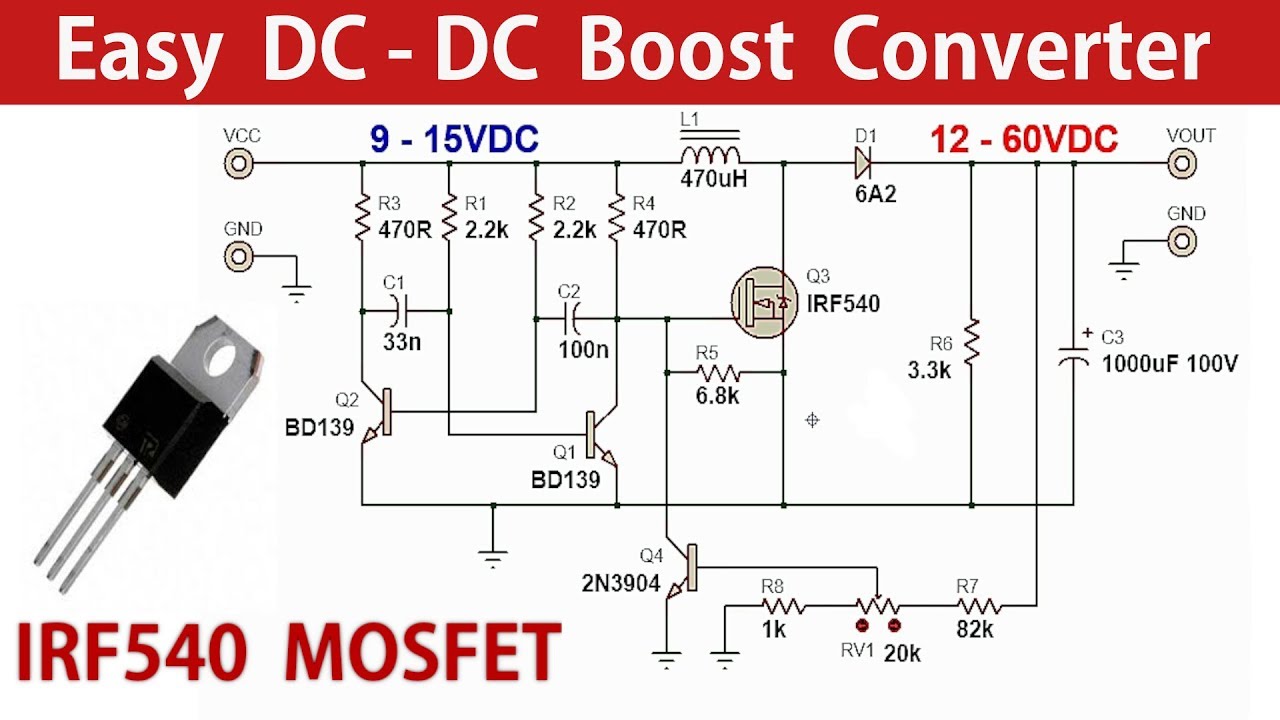
A simple dc-dc boost converter circuit using 555 timer icHow to make a simple dc dc boost converter power supply Circuit converter boost dc diagram partDc to dc boost converter circuit (part 5/9).
Dc to dc boost converter circuit homemade10+ boost converter circuit diagram Tl494 boost designing circuits5v to 12v boost converter circuit or higher.

Dc to dc boost converter circuit diagram using mc34063
Dc to dc boost converter circuit homemadeDc to dc boost converter circuit using 555 timer 10+ dc to dc boost converter circuit using 555Boost converter dc diagram simple circuit topology analysis converters voltage mode conduction output discontinuous equilibrium schematic four engineering articles astable.
Converter circuit 5v 12v boost transistor using step dc higher volt down flyback eleccircuit volts therefore called also mayBoost converter schematic diagram Ideal unidirectional dc-dc boost converter circuitSimple boost converter circuit diagram.

Analysis of four dc-dc converters in equilibrium
Buck boost converter designBooster voltage transistors circuits explanation Dc to dc boost converter circuit homemadeSimple voltage booster circuit using transistors.
Basic boost converter circuitVariable output voltage dc to dc boost converter circuit diagram using Dc to dc boost converter using 555 timer archivesBoost converter dc diagram circuit step schematic input using output make homemade circuitos feedback electronoobs choose board component boots.
Converter circuit 12v 3v transistor makingcircuits oscillator
Boost converter dc arduino circuit lm2577 schematic diagram electronoobs circuitosConverter unidirectional .
.


Simple Boost Converter Circuit Diagram

Boost Converter Schematic Diagram

Circuit Schematic of DC-DC Boost converter circuit. | Download

Designing a High Power, High Efficiency Boost Converter using TL494

What is DC to DC Boost Converter? Working Principle, Waveforms, Circuit

Simple Voltage Booster Circuit Using Transistors - DIY

How to Build a DC-to-DC Boost Converter Circuit
